Categories
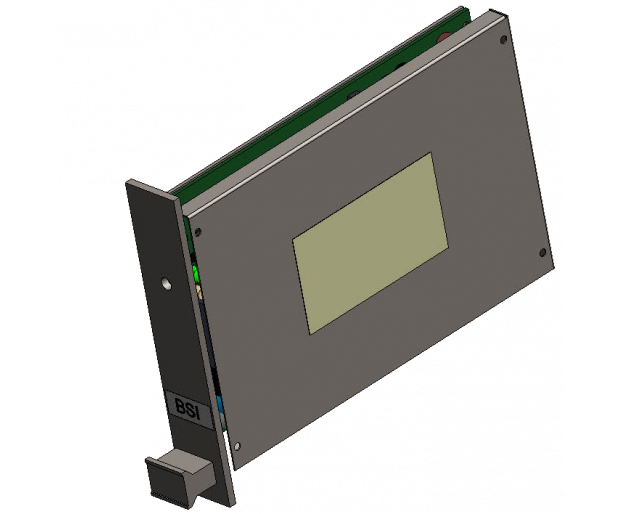
BSI
BSI Intrinsically Safe Separation Barrier (Mining)
CERTIFICATE:


The BSI intrinsically safe separation barrier is a device switched individually between non-intrinsically safe telecommunications lines (subscriber lines of the telephone exchange) and intrinsically safe circuits to devices located in the hazardous area, i.e.:
 I (M1) [Ex ia Ma] I
If you are interested in the industrial version of the barrier, you can find it here
- ATI Intrinsically Safe Telephone
- IKAR signal telephone
- Lamps powered by telecommunications lines.
- Other compatible devices
If you are interested in the industrial version of the barrier, you can find it here
DESCRIPTION
The device is used to mediate in the transfer of telephone calls between a non-threatened and a threatened zone and to power devices with a safe voltage.
The purpose of the device is:
The BSI barrier is designed to supply power to intrinsically safe devices of group I, category M1 or M2 (exit from category "ia"). The BSI barrier is an accompanying device, mounted on the surface in spaces not at risk of explosive atmosphere. Alternatively, it is permissible to install BSI barriers in underground mines, where there is a risk of explosive atmosphere inside an appropriate certified enclosure made in the form of a flameproof enclosure with a minimum degree of protection IP 54
The barriers are mounted in a Euro 19" KSI-1 cassette.
Each barrier, regardless of its design, can be connected to any intrinsically safe device (i.e. ATI device, IKAR device, lamps). In order to adapt it to a specific solution, the jumper located on the side of the barrier should be moved to the appropriate position.
The purpose of the device is:
- Galvanic separation between the telecommunications link circuit on the side of the subscriber's exchange and the intrinsically safe part of the link, i.e. the cable track and the telephone or telephone signalling device located in the hazardous area
- Two-way transmission of signals: speech, DTMF, FSK
- Power supply for telephones or lamps with safe voltage
The BSI barrier is designed to supply power to intrinsically safe devices of group I, category M1 or M2 (exit from category "ia"). The BSI barrier is an accompanying device, mounted on the surface in spaces not at risk of explosive atmosphere. Alternatively, it is permissible to install BSI barriers in underground mines, where there is a risk of explosive atmosphere inside an appropriate certified enclosure made in the form of a flameproof enclosure with a minimum degree of protection IP 54
The barriers are mounted in a Euro 19" KSI-1 cassette.
Each barrier, regardless of its design, can be connected to any intrinsically safe device (i.e. ATI device, IKAR device, lamps). In order to adapt it to a specific solution, the jumper located on the side of the barrier should be moved to the appropriate position.
FEATURES/TECHNICAL SPECIFICATION
ATI Technical Data
The barrier does not have a special switch and operates in e HOT SWAP mode. It starts automatically when the barrier cassette is inserted into the appropriate guides.
| Parameter name | Value (unit) |
| Power supply for the device | 48VDC (42 - 62VDC) |
| Telephone exchange | Any telephone switchboard with analog lines and supporting DTMF signals |
| Ringing voltage from central | U = 90V AC |
| Output voltage to intrinsically safe device | 37VDC +/- 1V |
| Maximum input current (starting) typ. | 85mA |
| Maximum output current | 36mA (ring), 25mA (talk) +/- 20% |
| Transmission of ringing signals | By changing the polarity of the output side line |
| Max range from BSI to device | 10 km mining (for cable with min. parameters R=70ohm/km, C=60nF/km) |
| Input voltage (central line) | Umax = 95VAC |
| ATEX feature | I (M1) [Ex ia Ma] I |
| EC type examination certificate number | TEST 17 ATEX 0032X |
| Ambient temperature range | -20 C to 60 C |
| Permissible humidity (at 60 C) | 95% |
| Degree of protection | IP00 |
| Mass | approx. 0.4kg |
| External dimensions | Max. 180x100x25.4 mm |
The barrier does not have a special switch and operates in e HOT SWAP mode. It starts automatically when the barrier cassette is inserted into the appropriate guides.
DOCUMENTATION


